Chapter Contents
- Chapter Glossary
- 8.1 Introduction
- 8.2 Avionics Systems Platform and Mission Development Considerations
- 8.3 State-of-the-Art (TRL 5-9): Command and Data Handling
- 8.4 State-of-the-Art (TRL 5-9): Flight Software
- 8.5 On the Horizon (TRL 1-4): Command and Data Handling
- 8.6 On the Horizon (TRL 1-4): Flight Software
- 8.7 Summary
- References
Chapter Glossary
| (AI/ML) | Artificial Intelligence/Machine Learning |
| (ASICs) | Application-specific Integrated Circuits |
| (CDH) | Command and Data Handling |
| (ConOps) | Concept of Operations |
| (COTS) | Commercial-off-the-shelf |
| (CRAM) | Chalcogenide RAM |
| (DDD) | Displacement Damage Dose |
| (DRAM) | Dynamic RAM |
| (EPS) | Electrical Power System |
| (FERAM) | Ferro-Electric RAM |
| (FPGAs) | Field Programmable Gate Arrays |
| (FSW) | Flight Software |
| (I/O) | Input & Output |
| (LEO) | Low-Earth Orbit |
| (MRAM) | Magnetoresistive RAM |
| (OBC) | Onboard Computer |
| (PCM) | Phase Change Memory |
| (PSA) | Payload and Subsystems Avionics |
| (Rad-hard) | Radiation-hardened |
| (SDRs) | Software-defined Radios |
| (SEEs) | Single-event Effects |
| (SEL) | Single-event Latch-up |
| (SEUs) | Single-event Upsets |
| (SoCs) | System-on-chip |
| (SRAM) | Static Random-Access Memory |
| (SSA) | Small Spacecraft Avionics |
| (SWaP) | Size, Weight, and Power |
| (SWaP-C) | Size, Weight, Power, and Cost |
| (TID) | Total Ionizing Dose |
8.1 Introduction
Small Spacecraft Avionics (SSA) consist of all the electronic subsystems, components, instruments, and functional elements of the spacecraft platform, including the primary flight sub-elements Command and Data Handling (CDH) and Flight Software (FSW), as well as other critical flight subsystems such as Payload and Subsystems Avionics (PSA). These subsystems are configured for specific mission platforms, architectures, and protocols, and are governed by appropriate operations concepts, development environments, standards, and tools. The CDH and FSW are the brain and nervous system of the integrated avionics system, and generally provide command, control, communication, and data management interfaces with all other subsystems in some manner, whether in a direct point-to-point, distributed, integrated, or hybrid computing mode. The avionics system is essentially the foundation for all components and their functions integrated on the spacecraft. As the nature of the mission influences the avionics architecture design, there is a large degree of variability in avionics systems.
There are two major factors to consider for SmallSat avionics:
- Spacecraft scale: a traditional spacecraft is a high-size, weight, power, and cost (SWaP-C), flagship system and typically has a high-SWaP-C avionics system to reduce risk and address higher reliability requirements. A SmallSat is a low-SWaP-C miniature system, with a low-SWaP-C avionics system. Typically, more risk is tolerable with low cost, but nonetheless enhancements can be applied to increase reliability. Individually, the avionics system scales with the spacecraft, however constellations of SmallSats can “match” the capabilities of a traditional spacecraft by distributing the avionics and increasing reliability through functional redundancy of the spacecraft.
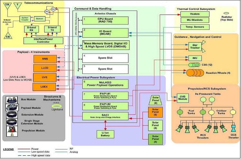
- Architecture design: the architecture design is not necessarily dependent on the scale of the spacecraft. In both traditional spacecraft and SmallSats, the avionics system can be either centralized or decentralized, single-string or redundant, and modular or monolithic. Traditional spacecraft reduce risk by employing redundancy such that if one element fails the entire architecture is able to continue, but SmallSat avionics designs are usually single-string, whereby if one element fails, the entire system fails. Figure 8.1 illustrates an architectural block diagram of a centralized small spacecraft system. In anticipation of extended durations in low-Earth orbit (LEO) and deep space missions, designers are now incorporating radiation-hardened (rad-hard) or radiation-tolerant architecture designs in their avionics packages to further increase their overall reliability.
While a significant focus of this chapter is on commercial products and developments, vendors are not the only ones developing avionics platforms; there are also numerous government and academic efforts worth considering, with a few examples below:
- SpaceCube and MUSTANG, by NASA GSFC (government)
- Sabertooth by JPL
- CHREC/SHREC Space Processor, by NSF SHREC (academic)
- RadPC by Montana State University (academic)
Given the distributed and integrated nature of modern avionics, this chapter organizes the state-of-the-art in SmallSat Avionics into CDH (8.3) and FSW (8.4). On-the-Horizon activities (TRL <5) for CDH and FSW (8.5 and 8.6, respectively) highlight recent developments in next-generation SSA systems. Avionics Systems Platform and Mission Development Considerations (8.2) discusses how these considerations are being addressed and/or mitigated by state-of-the-art advances in CDH, FSW, and PSA products. A summary of future SSA systems is provided in (8.7).
The information described below is not intended to be exhaustive but provides an overview of current state-of-the-art technologies and their development status for a particular small satellite subsystem. The list of organizations/companies in this chapter is not all-encompassing and does not constitute an endorsement from NASA. There is no intention of mentioning certain companies and omitting others based on their technologies or relationship with NASA. The information is for awareness and guidance only. The performance advertised may differ from actual performance since the information has not been independently verified by NASA subject matter experts and relies on information provided directly from the manufacturers or available public information. It should be noted that TRL designations may vary with changes specific to the payload, mission requirements, reliability considerations, and/or the environment in which performance was demonstrated. Readers are highly encouraged to reach out to companies for further information regarding the performance and TRL of the described technology.
8.2 Avionics Systems Platform and Mission Development Considerations
There are many factors considered in selecting the configuration and implementation of avionics subsystems, components, and elements for small spacecraft missions. Overall spacecraft concerns of Size, Weight, and Power (SWaP) always need to be considered. Some of the more pertinent issues and concerns that all small spacecraft missions must address include:
- Mission applicability and tailoring
- Element, module, and component modularity and interoperability
- Manufacturing and production efficiency, complexity, and scaling
- Mission environment, especially radiation and long-duration space exposure
- Standards and regulatory concerns
- SWaP-C constraints
In addition to CDH and FSW, state-of-the-art SSA systems should consider the following subsystem/payload specific electronic systems:
- Small spacecraft platform size ranges and configurations
- Integrated avionics platform architectures
- Mission avionics configurations
- Spacecraft and mission autonomy
Flight payload and subsystems avionics elements include:
- Subsystem integrated onboard computer (OBC) controllers
- Integrated systems health avionics
- Onboard payload processors
- Cloud-based processors
Modular avionics architectures for small spacecraft can be characterized as either federated or integrated. In a federated avionics architecture, each subsystem of the spacecraft is considered an independent, dedicated autonomous element, with the avionic components performing all functions independently and exchanging data over standardized communications protocols and interfaces. An integrated avionics architecture is a shared, distributed functionality, that can be configured with distributed, heterogeneous and/or mixed criticality elements. In either case, modular avionics architectures can be configured with smart subsystem capabilities, redundancy, fault tolerance, radiation mitigation, and anomaly mitigation procedures.
Constellation networks and swarms, synchronized formations, and other multi-satellite cluster formations are creating new opportunities for SSA. The increased need for synchronization, intersatellite communications, controlled positioning for integrated CDH functionality, coordination and conduct, Concept of Operations (ConOps), and autonomous operations impose new constraints on the avionics system. This is true not only for single satellites, but now also for multi-satellite configurations, whereby overall mission performance is dependent on all the platform elements acting in a co-dependent fashion.
8.3 State-of-the-Art (TRL 5-9): Command and Data Handling
Current trends in small spacecraft CDH generally appear to be following those of previous, larger scale CDH subsystems. The current generation of microprocessors can easily handle the processing requirements of most CDH subsystems and will likely be sufficient for use in spacecraft bus designs for the foreseeable future. Cost and availability are likely primary factors for selecting a CDH subsystem design from a given manufacturer, but many groups develop their own custom platforms. The ability to spread nonrecurring engineering costs over multiple missions and reduce software development through reuse are both desirable factors in a competitive market. Heritage designs work well for customers looking to select components with proven reliability for their mission as long as the key components are still in production. SmallSat CDH should consider the following:
- Avionics and onboard computing form factors
- Highly integrated onboard computing products
- Radiation-tolerant processors and FPGAs
- Memory, electronic function blocks, and components
- Bus electrical CDH interfaces
- Radiation mitigation and tolerance schemes
As small satellites move from the early CubeSat designs with short-term mission lifetimes to potentially longer missions, radiation tolerance becomes a significant factor when selecting parts. These distinguishing features, spaceflight heritage and radiation tolerance, are the primary differentiators in the parts selection process for long-term missions, verses those which rely heavily on commercial-off-the-shelf (COTS) parts. Experimental missions typically focus on low-cost, easy-to-develop systems that take advantage of open-source software and hardware to provide an easy entry into space systems development, especially for hobbyists or those who lack specific spacecraft expertise.
Small spacecraft CDH technologies and capabilities have been continuously evolving, enabling new opportunities for developing and deploying next-generation SSA. When small spacecraft were first introduced, a primary purpose was to observe and send information back to Earth. As awareness and utility have expanded, there is a need to improve the overall capability of data collection for specific mission environments beyond LEO. Small spacecraft, including nanosatellites and CubeSats, currently perform a wide variety of science in LEO, and these smaller platforms are emerging as candidates for more formidable missions beyond LEO.
The adoption of CubeSat and SmallSat technology is enabled by the miniaturization of electronics, sensors, and instruments. As spacecraft manufacturers begin to use more space-qualified parts, they find that those devices can often lag their COTS counterparts by several generations in performance but may be the only means to meet the radiation requirements placed on the system. Presently, there are several commercial vendors who offer highly integrated systems that contain the onboard computer, memory, electrical power system (EPS), and the ability to support a variety of Input & Output (I/O) for the CubeSat class of small spacecraft. Several CDH developments for CubeSats have resulted from in-house development, the rise of new companies that specialize in CubeSat avionics, and the use of parts from established companies who provide spacecraft avionics for the space industry in general. While parallel developments are impacting the growth of CubeSats, vendors with ties to the more traditional spacecraft bus market are increasing CDH processing capabilities within their product lines.
In-house designs for CDH units are being developed by some spacecraft bus vendors to better accommodate small vehicle concepts. While these items generally exceed CubeSat form factors in size, they can achieve similar environmental performance and may be useful in small satellite systems that replicate more traditional spacecraft subsystem distribution.
8.3.1 Avionics and Onboard Computing Form Factors
The CompactPCI and PC/104 form factors continue generally to be the industry standard for CubeSat CDH bus systems, with multiple vendors offering components that can be readily integrated into space-rated systems. Overall, form factors should fit within the standard CubeSat dimension of less than 10 × 10 cm2. Spacecraft avionics components are performance-driven and not necessarily dependent on spacecraft platform sizes, but some noncontainerized spacecraft platforms may need to consider the availability and utility of higher TRL avionics products. The PC/104 form factor was the original inspiration to define standard architecture and interface configurations for CubeSat processors, but with space at a premium, many vendors have been using all available space exceeding the formal PC/104 board size. Although the PC/104 board dimension continues to inspire CubeSat configurations, some vendors have made modifications to stackable interface connectors to address reliability and throughput concerns. Many vendors have adopted the use of stackable “daughter” or “mezzanine” boards to simplify connections between subsystem elements and payloads, and to accommodate advances in technologies that maintain compatibility with existing designs. A few vendors provide a modular package which allows users to select from a variety of computational processors.
8.3.2 Highly Integrated Onboard Computing Products
A variety of vendors are producing highly integrated, modular, onboard computing systems for small spacecraft. These CDH packages combine processors and/or Field Programmable Gate Arrays (FPGAs) with various memory banks, and with a variety of standard interfaces for other subsystems onboard. FPGAs and software-defined architectures also give designers a level of flexibility to upload software modifications to adapt to new requirements and interfaces. Table 8-1 summarizes the current state-of-the-art for some of these components. It should be noted that while some products have achieved TRL 9 by virtue of a space-based demonstration, what is relevant in one application may not be relevant to another, and different space environments and/or reliability considerations may result in lower TRL assessments. Some larger, more sophisticated computing systems have significantly more processing capability than what is traditionally used in SmallSat CDH systems, however the increase in processing power may be a useful tradeoff if payload processing and CDH functions can be combined (note that overall throughput should be analyzed to assure proper functionality under the most stressful operating conditions).
System developers are gravitating towards ready-to-use hardware and software development platforms that can provide seamless migration to higher performance architectures. As with non-space applications, there is a reluctance to change controller architectures due to the cost of retraining and code migration. Following the lead of microprocessor and FPGA vendors, CubeSat avionics vendors are now providing simplified tool sets and basic, cost-effective evaluation boards.
| Table 8-1: Sample of Highly Integrated Onboard Computing Systems | |||||||
|---|---|---|---|---|---|---|---|
| Manufacturer Headquarters | Product | Processor/ SoC/ FPGA | Radiation Hardness Assurance (RHA) | Board Dimension (cm) | Power Consumption (W) | Orbits Flown | Ref |
| AAC Clyde Space Sweden | Kryten-M3 | Smart Fusion 2 SoC including an ARM Cortex-M3 processor delivering 62.5 DMIPS | TID 20 krad (system level) | 9.589×9.017×0.551 | 0.4 | LEO | (1) |
| Sirius OBC & TCM | 32-bit LEON3FT (IEEE-1754 SPARC v8) fault-tolerant processor | TID 20 krad (system level) | 9.589×9.017×1.720 | 1.3 | LEO, lunar lander | (2) | |
| Alén Space Spain | DARA OBC | ARM 32-bit Cortex-M7 with FPU | N/A | 8.93×9.33×1.2 | Max: 0.280 | LEO, 2024 | (4) |
| TRISKEL OBC+TTC | ARM 32-bit Cortex-M7 with FPU | N/A | 8.93×9.33×1.2 | OBC_max:0.280 TTC_max: 5.865 | LEO, 2025 | (3) | |
| Aitech Systems Inc. | SP0-S | Power PC 1020, Alcatel RTAX | 100 krad TID, SEL/LET 40 Mev-cm2/mg (without enclosure) | 3U cPCI: 10.06x16x20.3 | 12 | LEO, MEO, GEO, Lunar, Deep Space* | (5) |
| SP1-S | 64-bit Arm® Cortex®-A72 cores @ 1.8 GHz | 100 krad TID (Target) | 3U Space VPX: 10.06x16x20.3 | <25 | TBD | ||
| S-A1760 | Pascal™ Architecture GPU w/256 CUDA® cores NVIDIA Denver 2 Dual-Core ARM® CPU + Cortex® A57 Quad-Core ARM® CPU | 1.05 krad TID, < 1 type 2 SEFI update in 158 days (without enclosure) | 12.7×12.7×5.2 | Configurable ≤ 5 Idle, 8-10 under typical CUDA load,<20 when System on Module is fully utilized | LEO* | (6) (7) | |
| S-C8780 | Intel® Pentium-D or Xeon-D, discrete 2D GPU, Xilinx UltraScale+ FPGA w/Dual-core ARM® CPU | TBD | 3U Open VPX: 10.06x16x20.3 | Configurable 25-55 | TBD | (8) | |
| S-C8500 | Intel® Tiger Lake UP3 SoC, 4 cores/8 threads, integrated GPGPU with 96 Execution Units, Xilinx UltraScale+ FPGA w/Dual-Core ARM® CPU is Optional | 1 krad TID, SEL/LET TBD (without enclosure) | 3U Open VPX: 10.06x16x20.3 | CPU Configurable from 12-28, Total system 22-42 configurations. | TBD | (9) | |
| Aerospacelab Belgium | OBC | Xilinx Zynq-7045 ARM dual-core Cortex A9 running at 667MHz Kintex-7 FPGA with 350k Programmable Logic Cells, 218,600 Look-up tables (LUT) and 437,200 flip-flops (FF) Linux and FreeRTOS compatible | Radiation hardened supervisor MCU Radiation hardened watchdog Heavy ions (62.5 MeV) No destructive event | 187×84.1×116.6 mm³ L x W x H Mass 1.325 kg | <4 | LEO | |
| Andes AerospaceChile | Andes OBC | 2x ARM 32-bit Cortex-M7 with FPU @ up to 550MHz | Estimated TID: 30krad (not tested) OBC+MRAM+NA ND full cold redundancy | 10x10x1.4 | Depends on configuration. Active: ~0.1 | Designed for LEO | |
| Argotec Italy | OBC FERMI | Dual-Core LEON3FT SPARC V8 Processor with fault-tolerant memory controller +Microchip RTG4 | Rad-hard | 10.24x10x4.49 | 5 (depending on load) | Deep Space, Lunar Orbit, LEO | (10) (11) |
| Berlin Space Technologies GmbH Germany | CDH-110 | STM32F103 | TID 30kRad (PCB level) | 17.6×9.4×6.9 | < 2 | LEO | |
| Bradford Space Netherlands | Stellar OBC + PDHS | Dual Polarfire SoC | 30 krad (Si) + functional SEE resilience through SW EDAC and internal cold redundancy | 13.3×11.5 | < 25W Full Load / < 3 Typical / < 1 Idle | TBD | (12) |
| C3S Electronics Development LLC Hungary | OBC | 32-bit ARM Cortex-M7 | Continuous integrity check on the program memory, multi-level watchdog system, MRAM storage | 0.92×0.895×0.123 without daughterboard, 0.92×0.895×0.136 with daughterboard | 0.46 (measured in test mode, using eMMC as mass storage) | LEO | (13) |
| CesiumAstro USA | SBC-1461 | 1.4 GHz ARM Cortex | Rad Tolerant | 5×8.4×1.3 | 8 typ. | LEO | (14) |
| RDP-23FV | Xilinx Versal | Rad Tolerant to Rad Hard | 16x10x2.54 | 50 | LEO (2025) | ||
| EnduroSat | OBC | ARM Cortex M7 | Tested at 40 krad TID | 8.9×9.4×2.3 (with integrated GNSS) | 1.5 Peak 0.2 Idle | 400-600 km SSO, equatorial | (15) |
| Payload Controller | Xilinx UltraScale+ SoC | Tested at 20 krad TID | 9.8x10x6.4 | <50 Peak 15Idle | Designed for LEO | ||
| GomSpace | NanoMind HP MK3 | Xilinx Zynq 7030/7045 | >20 krad | 9.5×9.5×3.15 | Dependent on customer application | LEO | (16) |
| Ibeos | EDGE-1100 (3U SpaceVPX) | AMD Ryzen SOC | TID: 30 krad SEE: >37 MeV | 3U SpaceVPX; 16(L) x 10(W) x 2.5(Pitch) | 6-35 | Designed for LEO and GEO | |
| EDGE-1100 Genie | AMD Ryzen SOC | TID: 30 krad SEE: >37 MeV | 14.8(L) x 10.8 (W) x 3.4(H) – Stand-alone box | 8-35 | Designed for LEO and GEO | ||
| Core-250 | High Performance Space Computer Processor (HPSC), 8 x RISC-V cores, 3U SpaceVPX | — | 16(L) x 10(W) x 2.5(Pitch) | <25 | Designed for LEO, GEO, and Beyond | ||
| Innoflight | CFC-400XS | Defense Grade Xilinx UltraScale+ MPSoC | TID: 30 krad | 8.2×8.2×2.7 | 6-25 | LEO (2021) & GEO (2022) | (17) |
| CFC-400XP | Defense Grade Xilinx UltraScale+ MPSoC | TID: 30 krad | 17.2x10x2.5 | 4-30 | LEO in 2024 | (18) | |
| CFC-510P | AMD Ryzen GPGPU | TID: 30 krad | 17.2x10x2.5 | 12-40 | LEO in 2024 | ||
| KP Labs | Antelope OBC and DPU | OBC – RM57 Herkules microcontroller (Dual 300 MHz ARM Cortex-R5F with FPU in lock-step) DPU – AMD Xilinx Zynq UltraScale+ MPSoC (ZU2EG, ZU3EG, ZU4EG, ZU5EG), Quad ARM Cortex-A53 CPU, Dual ARM Cortex-R5 in lock-step | COTS with SEE mitigation | Motherboard – 1x1x1 Daughterboard – 7x4x2 | From less than 0.5 (DPU is off) to 6 (DPU processes the data) | LEO | (19) |
| Leopard DPU | AMD Xilinx Zynq UltraScale+ MPSoC (ZU6EG, ZU9EG, ZU15EG); Quad ARM Cortex-A53 CPU; Dual ARM Cortex-R5 in lock-step | COTS with SEE mitigation | Non-redundant: 9×9.5×5 Redundant: 9×9.5×7.8 | 7 static power consumption; up to 10 for deep learning inference | LEO | (20) | |
| Lion DPU | AMD Xilinx Kintex Ultrascale FPGA (KU035, KU060, KU095) | COTS with SEE mitigation | 16x10x5 | <15 for KU035 version | TBD | (21) | |
| Laboratory for Atmospheric and Space Physics | LASP Generic Small-sat FPGA Board | Kintex-7 | 25 krad | 8.763×8.763 | 1 | LEO | (24) |
| Micro Aerospace Solutions | MAS-SBC-107 | Arm® Cortex®-M7 | Total Ionizing Dose of 30 krad (Si) | 9×9.6 | <30 | LEO | |
| Nara Space Technology | NSTOBC | Atmel ARM 9 based Microprocessor Unit | <24 krad | 9x9x1.6 | 0.429 (Idle) | LEO | (22) |
| NOVI | Gen 2 OBC | AMD/Xilinx Versal (AI Edge Series): Dual-core ARM® Cortex®-A72, Dual-core ARM® Cortex®-R5F, Programmable Logic (FPGA), AI Engines. Vorago ARM MCU: Low-power ARM® Cortex®-M4, Embedded rad-hard FRAM. | Radiation-hardened Vorago ARM MCU, SEL immune Xilinx processor, Optional radiation-hardened memory, Built in SEU/SEFI mitigation, ECC protected memory interfaces, Redundant storage for boot images. | 9.3×9.3×2.5 | <0.75W (Low Power Mode) 5-50W (High Performance Modes, Application Dependent) | LEO | (23) |
| Novo Space | SBC002AV | Zynq Ultrascale+ | TID: 30 krad; Automotive parts with Rad-tolerant in high criticality parts; Rich telemetry with local event response; Board sectorization and power control; ECC in Volatile memories; CRC / Reed-Solomon / Interleaving in Non-Volatile memories; FPGA and fabric use selective TRM on critical functionality; Scrubbing on soft FPGAs. | 16×10 | application dependent active mode max: 15 | TBD | (25) |
| SBC003AV | SmartFusion2 | 16×10 | application dependent active mode max: 8 | TBD | (26) | ||
| SBC004AF | Versal ACAP | 16×10 | Under development | TBD | (27) | ||
| SBC005AF | Polarfire | 16×10 | application dependent active mode max: 8 | TBD | (28) | ||
| GPU001AF | Jetson TX2i | 8.7×5 | active mode min:9 active mode max:15 | TBD | (29) | ||
| GPU002AF | Jetson Orin Nano | TID: 30 krad | 8.7×5 | active mode min:6 active mode max:11 | TBD | (30) | |
| Pumpkin Space Systems | PPM A1 | MCU+DSP | N/A | 90×96 | 0.05 | LEO | |
| Pumpkin Space Systems | PPM A2 | MCU+DSP | N/A | 90×96 | 0.05 | LEO | |
| PPM A3 | MCU+DSP | N/A | 90×96 | 0.05 | LEO | ||
| PPM B1 | MCU+DSP | N/A | 90×96 | 0.05 | LEO | ||
| PPM D1 | MCU | N/A | 90×96 | 0.05 | LEO | ||
| PPM D2 | MCU+DSP | N/A | 90×96 | 0.05 | LEO | ||
| PPM E1 | MCU | N/A | 90×96 | 0.05 | LEO | ||
| PPM B1 | MCU+DSP | N/A | 90×96 | 0.05 | LEO | ||
| PPM D1 | MCU | N/A | 90×96 | 0.05 | LEO | ||
| MBM2 w/BBB | MCU | ~5 krad | 90×96 | 2 | LEO | ||
| Ramon Space | NuPod | Space Grade Xilinx Versal ACAP, Cortex A72 4x / 16x Core ARM | TID: 30 krad SEL: 43 MeV·cm2/mg | 28.7×21.5×7.5 Mounted enclosure | 20-90 | TBD | (31) |
| Resilient Computing | RadPC-SBC-001 | RISC-V 32-Bit (AMD Artix 7) | COTS with SEE mitigation | 10×10 | 1.5 | LEO, Lunar (2024) | (32) |
| Sierra Space | UMCD | Microchip RTSX72 | 100kRad TID (Si) | 11.4×11.4×4.4 | 7 | LEO, GEO | (33) |
| SkyLabs | NANOhpc-obc | 4x RISC-V 64-bit / PolarFire / SoC | COTS w/ SEE mitigation | 9.5×9.1×1.3 | ~10 Peak | TBD | (34) (36) |
| NANOhpm-obc | 32-bit RISC-V core / PolarFire | COTS w/ SEE mitigation | 9.5×9.1×1.3 | <5 | LEO, MEO | (35) (38) | |
| NANOobc-2 | PicoSkyFT / IGLOO 2 | COTS w/ SEE mitigation | 9.5×9.1×1.1 | <1 Peak, <0.9 Idle | LEO, MEO | (37) | |
| Space Dynamics Laboratory | SDL-25 | UT700 LEON3-FT + RT3P FPGA | 10 krad | 13×9 | 2-6 | LEO, GEO | |
| LEON 4 | GR740 LEON4 + RTG4 | 50 krad | SpaceVPX 6U | 12 | LEO, GEO | ||
| SPiN USA | MA61C CubeSat | GR712RC dual-core 32-bit LEON3 fault-tolerant, SPARC V8 processor | Processor is 300 krad | 9.599×9.027 | 1-1.2 | TBD | (39) |
| MA61C smallsat | GR712RC dual-core 32-bit LEON3 fault-tolerant SPARC V8 processor | Processor is 300 krad | 10.5×10.5 | 1-1.2 | TBD | (40) | |
| MA61C cPCI serial space | GR712RC dual-core 32-bit LEON3 fault-tolerant SPARC V8 processor | Processor is 300 krad | 16×10 | 1-1.2 | TBD | (41) | |
| Spiral Blue | Space Edge One | Nvidia Jetson Xavier NX | N/A | 10×10 | 7 | LEO | (42) |
| Southwest Research Institute® (SwRI®) | Centaur SBC | GR712RC dual core LEON3-FT CPU, Xilinx Ultrascale or Microchip RT-ProAsic or RTG4 FPGA | TID: Up to 60 krad (Si), more with shielding SEL: Immune to >67eV/mg/cm2 SEU: < 1 error per 24-hour period | Available in 3U/6U cPCI form factors | Low power < 4 Operation | LEO | |
| HP-SBC | PowerPC based MPC8548e CPU, Microsemi RT-ProASIC FPGA, Optional: Microsemi RTG4 FPGA, Optional: Xilinx Ultrascale FPGA | TID: Up to 60 krad (Si), more with shielding SEL: Immune to >67eV/mg/cm2 SEU: < 1 error per 24-hour period | Available in 3U/6U cPCI form factors | 12-20 depending on clock frequency and FPGA pairing | Leo and GEO | (43) | |
| Spacemanic | DeepThought_OBC | SAMV71 | - | 6.7×4.2×0.7 | 0.1 | GRBAlpha BDSat1 & 2 Planetum Veronika CroCube | (44) |
| Eddie_OBC | MSP430 | – | 6.7×4.2×0.7 | 0.1 | LEO (500-550 SSO), Planetum Veronika CroCube | (45) | |
TelePIX Co., Ltd. | TetraPLE X OBP | 1. Microchip PolarFire® SoC (MPFS250T) – 64-bit RV64GC Quad Application processing cores (667 MHz) – 64-bit RV64IMAC monitor processor core (667 MHz) 2. NVIDIA® Jetson ORIN NX 16GB System-on-Module – 64-bit Cortex A78AE Armv8.2 (Eight-core) with Ampere GPU (1024 NVIDIA® CUDA® cores 32 Tensor cores) | N/A | 10x10x10 | 36 (max) | LEO (SSO) | (46) |
| Trident Space Electronic Systems | VDRT | Versal VC1902 | 30 krad / 50MeV LU | 10×14.6×2.54 | <60 | LEO/MEO capable | (46) |
| UDRT | MPSoC ZU19 | 30 krad / 40MeV LU | 10×14.6×2.54 | <50 | Multiple LEO 400-1200km missions | (47) | |
| Unibap | iX10-100A | AMD Ryzen V1000 (CPU and GPU), Intel Myriad-X (VPU) | Radiation Tolerant COTS with SEE mitigation | 10x10x6 | 25-40 | LEO | (48) |
| iX5-106 | AMD Steppe Eagle (CPU and GPU), Intel Myriad-X (VPU) Microchip SmartFusion2 (FPGA) | Radiation Tolerant COTS with SEE mitigation | 10x10x5 | 15-25 | |||
| Xiphos | Q7S | AMD-Xilinx Zynq-7020 Dual-core ARM Cortex-A9 | 25 krad | 7.8×4.3×0.9 | 2 | LEO | |
| Q8S | AMD-Xilinx Zynq Ultrascale+ MPSOC Quad-core ARM Cortex-A53 | 30 krad | 8x8x1.12 | >5 | LEO | ||
| Q8Js | AMD-Xilinx Zynq Ultrascale+ MPSOC Quad-core ARM Cortex-A53 | 30 krad | 8x8x1.12 | >5 | LEO | ||
| *Orbits flown are on larger spacecraft | |||||||
8.3.3 Radiation-Hardened Processors
Several radiation-hardened embedded processors have recently become available. These are being used as the core processors for a variety of purposes including CDH. Some of these are the Vorago VA10820 (ARM M0) and the VA41620 and VA41630 (ARM M4); Cobham GR740 (quad core LEON4 SPARC V8); BAE 5545 quad core processor; and LS1043 quad processor. These have all been radiation tested to at least 50 kRad total ionizing dose and a high onset for single-event effects.
8.3.4 Memory, Electronic Function Blocks, and Components
The range of onboard memory for small spacecraft is wide, typically starting around 32 kB and increasing with available technology. For CDH functions, onboard memory requires high reliability. A variety of different memory technologies have been developed for specific traits, including volatile memory, such as Static Random-Access Memory (SRAM) and Dynamic RAM (DRAM), Magnetoresistive RAM (MRAM), Ferro-Electric RAM (FERAM), Chalcogenide RAM (CRAM) and Phase Change Memory (PCM). SRAM is typically used due to price and availability, with numerous SRAM choices (up to 4M x 39 [20 MB]). There are many manufacturers that provide a variety of electronic components that are space-rated with high reliability. A chart comparing the various memory types and their performance is shown in Table 8-2.
| Table 8-2: Comparison of Memory Types | ||||||
|---|---|---|---|---|---|---|
| Feature | SRAM | DRAM | Flash | MRAM | FERAM | CRAM/ PCM |
| Non-volatile | No | No | Yes | Yes | Yes | Yes |
| Operating Voltage, ±10% | 2.5 – 5 V | 1.35-3.3 V | 3.3 & 5 V | 3.3 V | 3.3 V | 3.3 V |
| Organization (bits/die) | 512 k × 8 | 128 M × 8 1Gb × 8 | 16 M × 8; 4G × 8 | 2M × 8 | 16 k × 8 | Unk |
| Data Retention (70°C) | N/A | N/A | 10 years | 10 years | 10 years | 10 years |
| Endurance (Erase/Write cycles) | Unlimited | Unlimited | 1E5 | 1E13 | 1E13 | 1E13 |
| Access Time | 10-25 ns | 25 ns | 50 ns after page ready; 200 µs write; 2 ms erase | 300 ns | 300 ns | 100 ns |
| Radiation (TID) | 50K – 1 Mrad | 50 krad | 30 krad | 1 Mrad | 1 Mrad | 1 Mrad |
| Temperature Range | MIL-STD | Industrial | Commercial | MIL-STD | MIL-STD | MIL-STD |
| Power | 500 mW | 300 mW | 30 mW | 900 mW | 270 mW | Unk |
| Package | 4 MB-20 MB | 128 MB 1GB | 128MB – 4 GB | 2 MB | 1.5 MB (12 chip package) | Unk |
8.3.5 Bus Electrical Interfaces
CubeSat class spacecraft continue to use interfaces that are common in the microcontroller or embedded systems world. Highly integrated systems, especially systems-on-chip (SoCs), FPGAs, and application-specific integrated circuits (ASICs), will typically provide several interfaces to accommodate a wide range of users and to ease the task of interfacing with peripheral devices and other controllers. FPGAs are commonly used for these interfaces because of their flexibility and ability to change interfaces as needed. Some of the most common bus electrical interfaces are listed below with applicable interface standards:
- Serial Communication Interfaces (SCI): RS-232, RS-422, RS-485 etc.
- Synchronous Serial Communication Interface: I2C, SPI, SSC and Enhanced Synchronous Serial Interface (ESSI)
- Networks: Ethernet, LonWorks, etc.
- Fieldbuses: CAN Bus, LIN-Bus, PROFIBUS, etc.
- Timers: PLL(s), Capture/Compare and Time Processing Units
- Discrete IO: General Purpose Input/Output (GPIO)
- Analog to Digital/Digital to Analog (ADC/DAC)
- Debugging: JTAG, ISP, ICSP, BDM Port, BITP, and DB9 ports
- SpaceWire: a standard for high-speed serial links and networks
- High-speed data: RapidIO, XAUI, SerDes and MGT protocols are common in routing large quantities of mission data in the gigabit per second speeds
8.3.6 Radiation Mitigation and Tolerance Schemes
Deep space and long-duration LEO missions compel developers to consider reliability requirements and possibly incorporate radiation-mitigation strategies into their respective spacecraft designs. CubeSats are often either composed of only COTS components or a hybrid combination of COTS and rad-hard and radiation-tolerant components. COTS components typically offer superior performance, energy efficiency, and affordability compared to their rad-hard alternatives; however, COTS devices tend to be highly susceptible to radiation. The advantages of COTS components have enabled low-cost CDH development, while also allowing developers to leverage start-of-the-art technologies in their designs. A hybrid design combines COTS and rad-hard components, such as COTS processor and memory with rad-hardened supporting electronics (e.g., EPS, watchdog, etc.), to maximize the benefits of both technologies. These designs may also incorporate radiation-mitigation techniques to further enhance overall system reliability.
For space applications, the effects of radiation on electronic devices can vary broadly (50). Radiation effects are often categorized into long-term cumulative effects and transient single-event effects (SEEs). Long-term effects include total ionizing dose (TID) and displacement damage dose (DDD). TID, measured in krad, is the ionizing radiation absorbed by the device material over time causing parametric or functional degradation of the device. DDD is the nonionizing damage caused by particle collisions with the device structure over time. SEEs occur when a single radiation particle strike deposits enough charge to cause an effect. SEEs can be destructive or nondestructive. Single-event upsets (SEUs) are nondestructive SEEs that can affect the logic state of a memory cell. Single-event latch-up (SEL) are destructive SEEs that manifest as parasitic structures in CMOS logic or bipolar transistor structures, potentially causing a high-current state.
Other areas of consideration for CDH elements include memory, imaging, protection circuits (watchdog timers, communications watchdog timers, overcurrent protection, and power control), memory protection (error-correction code memory and software error detection and correction), communication protection (several components), and parallel processing and voting.
8.4 State-of-the-Art (TRL 5-9): Flight Software
The FSW, at a fundamental level, communicates the instructions for the spacecraft to perform all operations necessary for the mission. These include all the science objectives as well as regular tasks (commands) to keep the spacecraft functioning and ensure the storage and communication of data (telemetry). The FSW is usually thought of as all the programs that run on the CDH avionics but should also include all software running on the various subsystems and payload(s).
There are many factors in selecting a development environment and/or operating system for a space mission. A major factor is the amount of memory and computational resources. There are always financial and schedule concerns. Another factor is what past software an organization may have used and their experiences with that software. The maturity of the software and its availability for the target subsystem or payload are additional factors to be considered in the final selection.
FSW complexity can refer to the architecture design (e.g., the interactions between subsystems, especially for spacecraft autonomy) as well as the number of operations to be performed. The more software is required to do, the bigger the task and cost. This complexity (and the associated verification effort) is what primarily drives the cost and schedule for a program or mission. Required reliability and fault management can also increase complexity and cost, regardless of the size of the spacecraft. Changing requirements is also a huge factor, which may be mitigated by involving the software team early in the planning process.
With the increase in processing capability with CDH and other processors, more capable FSW has been enabled. Traditionally, larger spacecraft require rad-hard processors which have poor performance, while CubeSats and SmallSats can take more risks with COTS processors that offer substantially more performance. Several advances have increased the processing capabilities available for CubeSats. Low-power ARM-based processors and embedded COTS SoCs, as well as advances in radiation hardened processors, have brought similar processing capabilities down to the small size of CubeSats. All of this has resulted in increased demands and requirements for FSW.
Generally, CDH and other subsystems need to be able to supervise several inputs and outputs as well as process and store data within a fixed time-period. These all need to be performed in a reliable and predictable fashion throughout the lifetime of the mission. The needs of each mission can vary greatly, but basic deterministic and reliable processing is a fundamental requirement. The following are important when considering FSW design:
- Implication of CDH processors on FSW
- Frameworks
- Operating systems
- Software languages
- Mission operations and ground support suites
- Development environment, standards, and tools
8.4.1 Implication of CDH Processors on FSW
The processor and memory available on the CDH can put significant limitations on the FSW. For some of the smaller jobs, or to reduce electronic complexity, smaller processors are used (distributed processing). These have typically been thought of as embedded processors, with many of them containing dedicated memory. Modern integrated space avionics, including heterogeneous and mixed criticality architectures, also impact operational constructs and can contribute to advanced configurations (such as multiple modular redundant systems architectures) which can allow advanced paradigms for radiation tolerance and system redundancies in critical small spacecraft missions.
8.4.2 Frameworks
In the context of SSA, a FSW framework can be described as a hierarchal architecture, sometimes referred to as a set of lego-like building block constructs, partitions, and functions. This emerging system-of-systems concept describes the large-scale integration of many independent, self-contained systems that work together to satisfy a global need. Examples of commonly used frameworks include:
- cFS (https://cfs.gsfc.nasa.gov)
- F’ (https://github.com/nasa/fprime)
- NanoSat Mission Operations Framework (https://nanosat-mo-framework.github.io/)
- Spacecloud (https://space-cloud.io/)
- ROS (https://www.ros.org/)
8.4.3 Operating Systems
Operating systems manage computer hardware, software resources, and provide common services for computer programs. Examples of commonly used operating systems include:
- VxWorks
- RTEMS
- FreeRTOS
- Linux
8.4.4 Software Languages
System programming involves designing and writing computer programs with software languages that allow the computer hardware to interface with the programmer and the user, leading to the effective execution of application software on the computer system. State-of-the-art small spacecraft have used C, C++, Python, Arduino and other software languages.
8.4.5 Mission Operations and Ground Support Suites
Although not directly used on the spacecraft, mission operations and ground support suites must also use software and systems for testing, and to monitor, command, control, and communicate with the spacecraft, as well as display status and disseminate data across all aspects of a space mission (including spacecraft performance and procedures, systems health, science and technology data handling and management, and telemetry tracking and control). For smaller spacecraft and missions, it is usually best to use the same ground support software for mission operations, integration and testing, and development and testing. There are numerous open-source and proprietary tools and programs available for these activities. A small set of tools that have been used at NASA are described below. For more information, please refer to the Ground Data System and Mission Operations chapter.
8.4.6 Development Environment, Standards, and Tools
Development environment, standards, and tools are used to design, develop, validate, and operate small spacecraft missions, with adherence to accepted software and space mission standards. Examples of commonly used development tools include:
- Version control tools
- Auto-generation of software
- Simulations and simulators
- Software best practices and NPR7150
8.5 On the Horizon (TRL 1-4): Command and Data Handling
Many CDH systems will continue to follow trends set for embedded systems. Short-duration missions in LEO will continue to take advantage of advances made by industry leaders who provide embedded systems, technologies, and components. In keeping with the low-cost, rapid development theme of CubeSat-based missions, many COTS solutions are available for spacecraft developers.
While traditional CDH processing needs are relatively stagnant, as small satellites are being targeted for flying increasingly data-heavy payloads (i.e., imaging systems) there is new interest in advanced onboard processing for mission data. Typically, these higher performance functions would be added as a separate payload processing element outside of the CDH function.
Next-generation SSA/PSA distributed avionics applications are integrating FPGA-based software-defined radios (SDRs) on small spacecraft (51). A SDR can transmit and receive in widely different radio protocols based on a modifiable, reconfigurable architecture, and is a flexible technology that can enable the design of an adaptive communications system. This can increase data throughput and enable software updates on-orbit, also known as re-programmability. Additional FPGA-based functional elements include imagers, Artificial Intelligence and Machine Learning (AI/ML) processors, and subsystem-integrated edge and cloud processors. The ability to reprogram sensors or instruments while on-orbit have benefited several CubeSat missions when instruments do not perform as anticipated, or when entering an extended mission phase that requires subsystems or instruments to be reprogrammed.
In keeping with trends seen in other disciplines and industries, the Industry 4.0 and “digitally managed everything” is absolutely of critical importance for technological and programmatic efficiencies in SSA systems development. Following are some modern tools, technologies, and approaches that should be considered when developing and deploying next-generation small spacecraft avionic systems:
- Artificial intelligence, machine learning, and machine vision
- Robotics and automation
- Model-based systems engineering
- Embedded systems / edge computing
- Internet-of-space-things
- Cloud computing
- Augmented reality/ virtual reality / mixed reality
- Software-defined-everything
- Advanced manufacturing
- Digital twin
8.6 On the Horizon (TRL 1-4): Flight Software
FSW is key to mission success. The field of software is a very dynamic environment that is continuously evolving. The challenges with flight software usually remain the same regardless of the size of the spacecraft (CubeSat to SmallSat) and are related to the size and complexity of the endeavor. Overall, FSW can be known to cause scheduling and implementation issues, especially during integration and test. There is usually a temptation to add additional features, and all these factors can drive up overall complexity of the FSW and increase risk to the mission as a whole.
It is essential that FSW be as simple as possible. It is critical to survey options and plan early in any FSW effort. Wherever possible, early development and testing should be performed. Efforts to add additional features should be looked at very critically with a strong effort to stick to the existing plan. With good planning and careful execution, a favorable outcome can be achieved. It is becoming more common to update software after the hardware is delivered (or even launched), and there are now software frameworks such as cFS that have features to enable software updates after deployment.
On the horizon FSW will soon include multicore processor operating systems and programming, as learning how to harness multicore processors differently than Microsoft Windows does will enable true real-time multiprocessing. On the horizon FSW will also include artificial intelligence (e.g., Nvidia); FSW for multicore, multiprocessor, and heterogenous platforms (e.g., AMD-Xilinx Versal); and FSW (middleware) for constellations of SmallSats with resource management, scheduling and task assignment, and fault tolerance.
Spacecraft autonomy is an emerging capability and SmallSat designers have particular interest in the following characteristics for autonomous systems:
- Situational and self-awareness
- Reasoning and acting
- Collaboration and interaction
- Engineering and integrity
Spacecraft autonomy can be considered part of management, direction, and control for all subsystems and functions in a spacecraft. CDH takes input from, and provides direction to, all subsystems (ADCS, Power, Propulsion, Comm, vehicle health, etc.). Those subsystems may also have a degree of autonomy depending on the complexity of its local “smart subsystems” processor. The NASA 2020 Technology Roadmap defines autonomous systems as a cross-domain capability that enables the system to operate in a dynamic environment independent of external control (52).
Some autonomous systems now implement a heterogeneous architecture, meaning they contain multiple processors with varying levels of performance and capabilities. For instance, higher performance modules and components can be used for sophisticated data processing, AI and onboard computing for both spacecraft and mission performance optimization—as well as real-time adaptive analysis of science data—while lower performance onboard processors and FPGAs conduct the routine spacecraft operations functions and interact with the subsystems which also may include distributed performance cascades.
Cybersecurity is also becoming a driving factor in FSW. This is mostly handled through the encryption of commands, but as space becomes more crowded, more sophisticated cybersecurity schemes may be required of SmallSats. SmallSats can also be a testbed for demonstrating new hardware and software for cybersecurity.
8.7 Summary
Space applications now require considerable autonomy, precision, and robustness, and are refining technologies for such operations as on-orbit servicing, relative and absolute navigation, inter-satellite communication, and formation flying. An exciting trend is that small spacecraft missions are becoming more complex as these platforms are now being used for lunar and deep space science and exploration missions. Small spacecraft technology is expanding to meet the needs of increasing small spacecraft mission complexity. This has accelerated over the past few years to achieve the next gen goals of using small spacecraft to collect important science in deep space, and mitigate risk for larger, more complex mission-critical situations. In parallel, spacecraft electronics have matured with higher performance and reliability, and with miniaturized components that meet the growing needs of these now very capable spacecraft.
The 2024 Small Spacecraft Avionics chapter has been updated with a broader, interrelated framework, where CDH, FSW, and smart payloads are not just independent space platform subsystems but are part of an integrated avionics ecosystem which includes all electronic elements of a space platform, now primarily digitally based and or managed. Also, SSA should not be considered as an isolated spaceflight technology component, but rather as a core digital engineering technology emphasis area, capable of taking advantage of and integrating products, processes, and technologies from other disciplines. To continue to be relevant and efficient, the SSA communities must remain cognizant and receptive of the continuously evolving nature of the digital based Industry 4.0 technology revolution now being evidenced in other related and/or associated vertical disciplines and solutions.
For feedback solicitation, please email: arc-sst-soa@mail.nasa.gov. Please include a business email for further contact.
References
- AAC Clyde Space. “Kryten-M3.” Datasheet. [Online] Available at: https://www.aac-clyde.space/wp-content/uploads/2021/10/AAC_DataSheet_Kryten.pdf
- AAC Clyde Space. “Sirius OBC and TCM.” Datasheet. [Online] Available at: https://www.aac-clyde.space/wp-content/uploads/2021/10/AAC_DataSheet_Sirius-OBC.pdf
- Alen Space. “TRISKEL OBC+TTC+OBSW Solution” datasheet. Accessed: December 1, 2023. [Online] Available at: https://alen.space/products/triskel
- Alen Space. “DARA OBC: On-Board Computer with Flight Heritage.” Datasheet. [Online] Available at: https://alen.space/products/dara-obc/
- Aitech Systems Inc. “SP0-S: Radiation Tolerant 3U CompactPCI SBC.” [Online] Available at: https://aitechsystems.com/product/sp0-s-rad-tolerant-3u-compactpci-sbc/
- Aitech Systems Inc. “S-A1760 Venus: Radiation-characterized Space AI GPGPU.” [Online] Available at: https://aitechsystems.com/product/s-a1760-space-gpgpu/
- Aitech Systems Inc. “Aitech’s Space-rated AI Supercomputer on NASA Atmospheric Re-entry Demonstration.” May 2023. [Online] Available at: https://aitechsystems.com/aitechs-space-rated-ai-supercomputer-on-nasa-atmospheric-re-entry-demonstration/
- Aitech Systems Inc. “C878:3U VPX SBC.” [Online] Available at: https://aitechsystems.com/product/c878-3u-vpx-sbc/
- Aitech Systems Inc. “U-C850x Series: Innovative SWaP-C-optimized Secure 3U.” [Online] Available at: https://aitechsystems.com/product/u-c850x-series-3u-vpx-secure-sbc/
- Argotec. “FERMI: Deep Space On-Board Computer.” Datasheet. [Online] Available at: https://www.argotecgroup.com/wp-content/uploads/2022/03/Argotec_FERMI_scheda_prodotto.pdf
- Argotec. “Hack: High-Performance Modular On-Board Computer,” Technical Datasheet. [Online] Available at: https://www.argotecgroup.com/wp-content/uploads/2022/03/Argotec_HACK_scheda_prodotto.pdf
- Bradford Space Deep Space Industries. “Deep Space Avionics.” Preliminary Datasheet.
- C3S Electronics Development LLC. “OBC.” Datasheet. [Online] Available at: https://c3s.hu/subsystems/#CHP-OBC
- Cesium Astro. “SBC-1461: Single-Board Computer.” [Online] Available at: https://www.cesiumastro.com/products/sbc-1461#specifications
- EnduroSat. “Onboard Computer (OBC).” [Online] Available at: https://www.endurosat.com/cubesat-store/cubesat-obc/onboard-computer-obc/
- GOMspace. “NanoMind HP MK3.” [Online] Available at: https://gomspace.com/shop/subsystems/command-and-data-handling/nanomind-hp-mk3-(1).aspx
- Innoflight. “CFC-400XS.” 2023. [Online] Available at: https://www.innoflight.com/product/cfc-400xs-2/
- Innoflight. “CFC-400XP.” 2023. [Online] Available at: https://www.innoflight.com/product/cfc-400xp/
- KP Labs. “Antelope” datasheet. [Online] Available at: https://kplabs.space/wp-content/uploads/Antelope-technical-sheet.pdf
- KP Labs. “Leopard” datasheet. [Online] Available at: https://kplabs.space/wp-content/uploads/Leopard-technical-sheet.pdf
- KP Labs. “Lion” datasheet. [Online] Available at: https://kplabs.space/wp-content/uploads/Lion-technical-sheet.pdf
- A. Na-young. “Nara Space’s nanosatellite conducts Earth observation mission.” January 29, 2024. [Online] Available at: https://en.yna.co.kr/view/AEN20240129003400320
- NOVI. “Products | Gen 2 OBC.” [Online] Available at: https://www.novillc.com/products
- Laboratory for Atmospheric and Space Physics, University of Colorado, Boulder. “State-of-the-art small satellite technology.” Accessed December 1, 2023. [Online] Available at: https://lasp.colorado.edu/our-expertise/engineering/smallsats/
- Novo Space. “SBC002AV.” [Online] Available at: https://www.novo.space/products/sbc002av
- Novo Space. “SBC003AV.” [Online] Available at: https://www.novo.space/products/sbc003av
- Novo Space. “SBC004AV.” [Online] Available at: https://www.novo.space/products/sbc004av
- Novo Space. “SBC005AV.” [Online] Available at: https://www.novo.space/products/sbc005av
- Novo Space. “GPU001AF – General purpose GPU.” [Online] Available at: https://www.novo.space/products/gpu001af
- Novo Space. “GPU002AF – General purpose GPU.” [Online] Available at: https://www.novo.space/products/gpu002af
- Ramon Space. “NuPod Compute.” [Online] Available at: https://drive.google.com/file/d/1VPc_ALFm3GKp4KTXxUkaOIrOEPWb2SUO/view
- Resilient Computing. “Technology: RadPC – Radiation Tolerant Computing.” [Online] Available at: https://resilient-computing.com/technology
- Sierra Space. Spaceflight Hardware Catalog. Page 320. [Online] Available at: https://www.sierraspace.com/spaceflight-hardware-catalog/
- SkyLabs. “NANOhpc-obc.” [Online] Available at: https://www.skylabs.si/products/nanohpc-obc/
- SkyLabs. “NANOhpm-obc.” [Online] Available at: https://www.skylabs.si/products/nanohpm-obc/
- SkyLabs. “TRISAT-R Successfully Reached Medium Earth Orbit.” July 14, 2022. [Online] Available at: https://www.skylabs.si/trisat-r-successfully-reached-the-medium-earth-orbit/
- SkyLabs. “NANOobc-2.” [Online] Available at: https://www.skylabs.si/products/nanoobc-2/
- D. Gačnik. “NANOsky I 2nd-Generation Satellite Platform For Multi-mission Constellation Projects.” Presented at 5th ESA CubeSat Industry Space Days, June 1-3, 2021. Available at: https://www.hermes-sp.eu/wp-content/uploads/2021/07/CID-SkyLabs-NANOsky-I-Platform_v7.pdf
- Space Products and Innovation. “Multipurpose Adapter Generic Interface Connector (MA61C).” Datasheet. Available at: https://www.spinintech.com/_files/ugd/0ac116_9b444733c51f401898e790bb26040144.pdf
- Space Products and Innovation. “Multipurpose Adapter Generic Interface Connector (MA61C) Datasheet.” Available at: https://534279dc-dca3-4d3e-b394-5d35d472455d.filesusr.com/ugd/0ac116_8d41f30b0a264087adf66848f2247b69.pdf
- Space Products and Innovation. “Multipurpose Adapter Generic Interface Connector (MA61C) cPCI Serial Space Version Datasheet.” Available at: https://www.spinintech.com/_files/ugd/0ac116_bad3b7ec01ce4e62ba5b06a9ad3e7c40.pdf
- Spiral Blue. “Space Edge Computer Datasheet.” April 2023. Available at: https://www.spiralblue.space/_files/ugd/8ebd97_1dee6e72951345a784a2974782a6164a.pdf
- Southwest Research Institute (SwRI). “Single Board Computers.” 2023. [Online] Available at: https://www.swri.org/industry/space-engineering/single-board-computers
- Spacemanic. “Deep Thought On-board Computer.” 2023. [Online] Available at: https://www.spacemanic.com/deep-thought-onboard-computer/
- Spacemanic. “Eddie Onboard Computer.” 2023. Accessed December 1, 2023. [Online] Available at: https://www.spacemanic.com/eddie-onboard-computer/
- TelePIX. Products: TetraPLEX. [Online] Available at: https://telepix.net/products/?current=TETRAPLEX&index=1
- Trident Space Electronic Systems. “Versal Digital RF Transceiver.” Datasheet. September 12, 2023. Available at: https://tridsys.com/wp-content/uploads/2023/10/Trident-VDRT-Cut-Sheet.pdf
- Trident Space Electronic Systems. “ZYNQ ULTRASCALE+ Digital RF Transceiver.” Datasheet. September 12, 2023. Available at: https://tridsys.com/wp-content/uploads/2023/10/Trident-VDRT-Cut-Sheet.pdf
- Unibap. “SpaceCloud’s 22 apps aboard the Wild Ride mission verified in orbit.” June 9, 2021. [Online] Available at: https://unibap.com/news/spaceclouds-22-apps-aboard-the-wild-ride-mission-verified-in-orbit/
- National Academies of Sciences, Engineering, and Medicine: “Testing at the Speed of Light: The State of U.S. Electronic Parts Space Radiation Testing Infrastructure.” Washington, DC: The National Academies Press. 2018.
- M. Wirthlin, “High-Reliability FPGA-Based Systems: Space, High-Energy Physics, and Beyond,” in Proceedings of the IEEE, vol. 103, no. 3, pp. 379-389, March 2015.
- NASA. 2020 Technology Taxonomy. [Online] Available at: https://www.nasa.gov/sites/default/files/atoms/files/2020_nasa_technology_taxonomy.pdf


