4.1 Stakeholder Expectations Definition
4.2 Technical Requirements Definition
4.3 Logical Decomposition
4.4 Design Solution Definition
Logical decomposition is the process for creating the detailed functional requirements that enable NASA programs and projects to meet the stakeholder expectations. This process identifies the “what” that should be achieved by the system at each level to enable a successful project. Logical decomposition utilizes functional analysis to create a system architecture and to decompose top-level (or parent) requirements and allocate them down to the lowest desired levels of the project.
The Logical Decomposition Process is used to:
- Improve understanding of the defined technical requirements and the relationships among the requirements (e.g., functional, performance, behavioral, and temporal etc.), and
- Decompose the parent requirements into a set of logical decomposition models and their associated sets of derived technical requirements for input to the Design Solution Definition Process.
4.3.1 Process Description
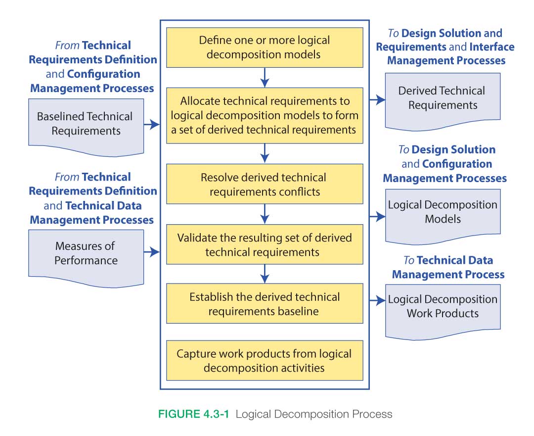
Figure 4.3-1 provides a typical flow diagram for the Logical Decomposition Process and identifies typical inputs, outputs, and activities to consider in addressing logical decomposition
4.3.1.1 Inputs
Typical inputs needed for the Logical Decomposition Process include the following:
- Technical Requirements: A validated set of requirements that represent a description of the problem to be solved, have been established by functional and performance analysis, and have been approved by the customer and other stakeholders. Examples of documents that capture the requirements are an SRD, PRD, and IRD.
- Technical Measures: An established set of measures based on the expectations and requirements that will be tracked and assessed to determine overall system or product effectiveness and customer satisfaction. These measures are MOEs, MOPs, and a special subset of these called TPMs. See Section 6.7.2.6.2 in the NASA Expanded Guidance for Systems Engineering at https://nen.nasa.gov/web/se/doc-repository for further details.
4.3.1.2 Process Activities
4.3.1.2.1 Define One or More Logical Decomposition Models
The key first step in the Logical Decomposition Process is establishing the system architecture model. The system architecture activity defines the underlying structure and relationships of hardware, software, humans-in-the-loop, support personnel, communications, operations, etc., that provide for the implementation of Agency, mission directorate, program, project, and subsequent levels of the requirements. System architecture activities drive the partitioning of system elements and requirements to lower level functions and requirements to the point that design work can be accomplished. Interfaces and relationships between partitioned subsystems and elements are defined as well.
Once the top-level (or parent) functional requirements and constraints have been established, the system designer uses functional analysis to begin to formulate a conceptual system architecture. The system architecture can be seen as the strategic organization of the functional elements of the system, laid out to enable the roles, relationships, dependencies, and interfaces between elements to be clearly defined and understood. It is strategic in its focus on the overarching structure of the system and how its elements fit together to contribute to the whole, instead of on the particular workings of the elements themselves. It enables the elements to be developed separately from each other while ensuring that they work together effectively to achieve the top-level (or parent) requirements.
Much like the other elements of functional decomposition, the development of a good system-level architecture is a creative, recursive, collaborative, and iterative process that combines an excellent understanding of the project’s end objectives and constraints with an equally good knowledge of various potential technical means of delivering the end products.
Focusing on the project’s ends, top-level (or parent) requirements, and constraints, the system architect should develop at least one, but preferably multiple, concept architectures capable of achieving program objectives. Each architecture concept involves specification of the functional elements (what the pieces do), their relationships to each other (interface definition), and the ConOps, i.e., how the various segments, subsystems, elements, personnel, units, etc., will operate as a system when distributed by location and environment from the start of operations to the end of the mission.
The development process for the architectural concepts should be recursive and iterative with feedback from stakeholders and external reviewers, as well as from subsystem designers and operators, provided as often as possible to increase the likelihood of effectively achieving the program’s desired ends while reducing the likelihood of cost and schedule overruns.
In the early stages of development, multiple concepts are generated. Cost and schedule constraints will ultimately limit how long a program or project can maintain multiple architectural concepts. For all NASA programs, architecture design is completed during the Formulation Phase. For most NASA projects (and tightly coupled programs), the baselining of a single architecture happens during Phase A. Architectural changes at higher levels occasionally occur as decomposition to lower levels produces complexity in design, cost, or schedule that necessitates such changes. However, as noted in Figure 2.5-1, the later in the development process that changes occur, the more expensive they become.
Aside from the creative minds of the architects, there are multiple tools that can be utilized to develop a system’s architecture. These are primarily modeling and simulation tools, functional analysis tools, architecture frameworks, and trade studies. (For example, one way of doing architecture is the Department of Defense (DOD) Architecture Framework (DODAF). A search concept is developed, and analytical models of the architecture, its elements, and their operations are developed with increased fidelity as the project evolves. Functional decomposition, requirements development, and trade studies are subsequently undertaken. Multiple iterations of these activities feed back to the evolving architectural concept as the requirements flow down and the design matures.
4.3.1.2.2 Allocate Technical Requirements, Resolve Conflicts, and Baseline
Functional analysis is the primary method used in system architecture development and functional requirement decomposition. It is the systematic process of identifying, describing, and relating the functions a system should perform to fulfill its goals and objectives. Functional analysis identifies and links system functions, trade studies, interface characteristics, and rationales to requirements. It is usually based on the ConOps for the system of interest.
Three key steps in performing functional analysis are:
- Translate top-level requirements into functions that should be performed to accomplish the requirements.
- Decompose and allocate the functions to lower levels of the product breakdown structure.
- Identify and describe functional and subsystem interfaces.
The process involves analyzing each system requirement to identify all of the functions that need to be performed to meet the requirement. Each function identified is described in terms of inputs, outputs, failure modes, consequence of failure, and interface requirements. The process is repeated from the top down so that sub-functions are recognized as part of larger functional areas. Functions are arranged in a logical sequence so that any specified operational usage of the system can be traced in an end-to-end path.
The process is recursive and iterative and continues until all desired levels of the architecture/system have been analyzed, defined, and baselined. There will almost certainly be alternative ways to decompose functions. For example, there may be several ways to communicate with the crew: Radio Frequency (RF), laser, Internet, etc. Therefore, the outcome is highly dependent on the creativity, skills, and experience of the engineers doing the analysis. As the analysis proceeds to lower levels of the architecture and system, and the system is better understood, the systems engineer should keep an open mind and a willingness to go back and change previously established architecture and system requirements. These changes will then have to be decomposed down through the architecture and sub-functions again with the recursive process continuing until the system is fully defined with all of the requirements understood and known to be viable, verifiable, and internally consistent. Only at that point should the system architecture and requirements be baselined.
4.3.1.2.3 Capture Work Products
The other work products generated during the Logical Decomposition Process should be captured along with key decisions made, supporting decision rationale and assumptions, and lessons learned in performing the activities.
4.3.1.3 Outputs
Typical outputs of the Logical Decomposition Process include the following:
- Logical Decomposition Models: These models define the relationship of the requirements and functions and their behaviors. They include the system architecture models that define the underlying structure and relationship of the elements of the system (e.g., hardware, software, humans-in-the-loop, support personnel, communications, operations, etc.) and the basis for the partitioning of requirements into lower levels to the point that design work can be accomplished.
- Derived Technical Requirements: These are requirements that arise from the definitions of the selected architecture that were not explicitly stated in the baselined requirements that served as an input to this process. Both the baselined and derived requirements are allocated to the system architecture and functions.
- Logical Decomposition Work Products: These are the other products generated by the activities of this process.
4.3.2 Logical Decomposition Guidance
Refer to Section 4.3.2 and Appendix F in the NASA Expanded Guidance for Systems Engineering at https://nen.nasa.gov/web/se/doc-repository for additional guidance on:
- Product Breakdown Structures and
- Functional Analysis Techniques.


