 |
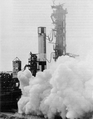
| Figure 66. Sequence Compatibility Firing of the two stages of Gemini launch vehicle 1 at pad 19, Jan. 21, 1964. (KSC Photo 64P-7, Jan. 21, 1964.) |
 |
| Figure 66. Sequence Compatibility Firing of the two stages of Gemini launch vehicle 1 at pad 19, Jan. 21, 1964. (KSC Photo 64P-7, Jan. 21, 1964.) |
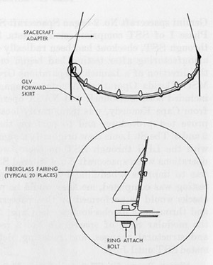 |
| Figure 67. The interface between Gemini launch vehicle and spacecraft. (NASA Photo S-64-3065, undated.) |
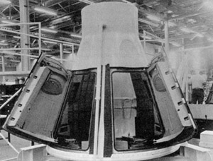 |
| Figure 68. Gemini boilerplate 3A in the production area at the McDonnell plant before being shipped to Weber Aircraft. (NASA Photo 1053, Feb. 18, 1964.) |
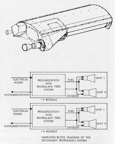 |
| Figure 69. The Agena secondary propulsion system. (Lockheed, "Gemini Agena Target Vehicle Familiarization Handbook," LMSC A602521, Apr. 1, 1964, pp. 4-1, 4-3.) |
 |
| Figure 70. Gemini-Titan 1 during Electronic-Electrical Interference Tests with the launch vehicle erector lowered. (NASA Photo No. 64-Gemini 1-44.) |
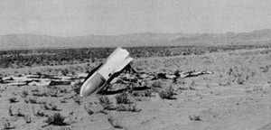 |
| Figure 71. Parachute test vehicle after drop test on July 16, 1964. (NASA Photo No. 64-H-2451, July 16, 1964.) |
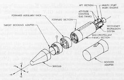 |
| Figure 72. Configuration of the Gemini Agena target vehicle. (Lockheed, "Gemini Agena Target Vehicle Familiarization Handbook," LMSC A602521, Apr. 1, 1964, p. 1-6.) |
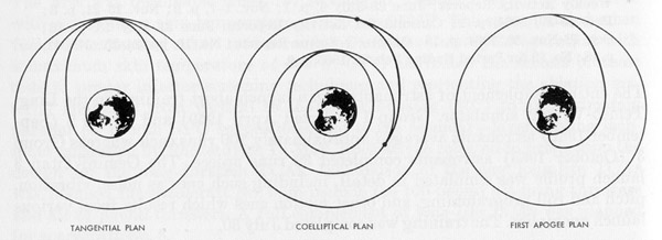 |
| Figure 73. The three basic rendezvous plans being considered for the first Gemini rendezvous mission. (MSC, Gemini Midprogram Conference, Including Experiment Results, NASA SP-121, 1966, p. 277.) |
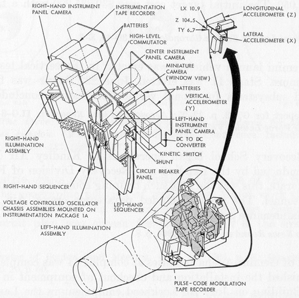 |
| Figure 74. Special instrumentation pallets to be installed in Gemini spacecraft No. 2 in the same positions that astronauts would occupy in later flights. (NASA Photo S-652263, undated.) |
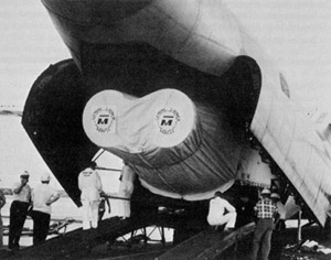 |
| Figure 75. The first stage of Gemini launch vehicle 2 being unloaded from an Air Force C-133 at Cape Kennedy. (KSC 64-14608, July 11, 1964.) |
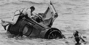 |
| Figure 76. At-sea egress training in Galveston Bay. (NASA Photo No. 65-H-641, released Apr. 14, 1965.) |
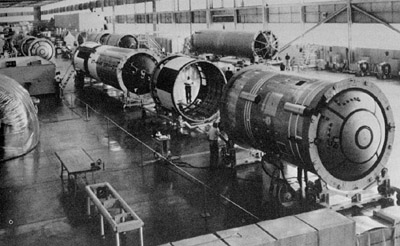 |
| Figure 77. Gemini launch vehicle 3 undergoing final checks before roll-out inspection. (Martin Photo No. B-70503, undated.) |
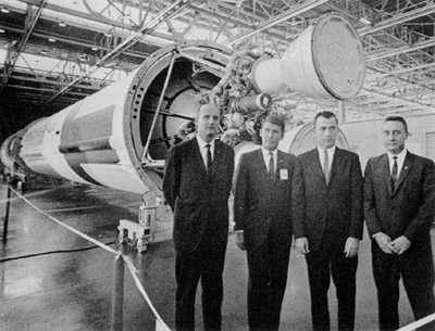 |
| Figure 78. Backup and prime crews for Gemini-Titan 3 mission at Gemini launch vehicle 3 roll-out inspection. Left to right: Thomas P. Stafford, Walter M. Schirra, Jr., John W. Young, and Virgil I. Grissom. (NASA Photo No. 64-H-2598 [Gemini], Oct. 28, 1964.) |
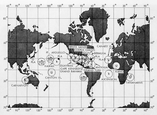 |
| Figure 79. The Gemini Network. See Appendix 4 tabulation of equipment at each site. (NASA Photo S-65-4007, undated.) |
 |
| Figure 80. Water egress training in the flotation tank at Ellington Air Force Base, Texas. (NASA Photo S-65-2503, Feb. 5,1965.) |
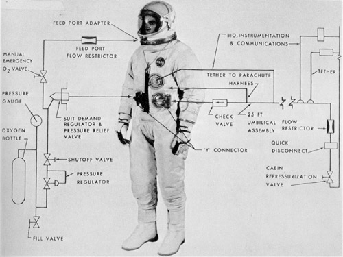 |
| Figure 81. Diagram of the Gemini G4C extravehicular suit. (NASA Photo S-65-4858, May 1965.) |
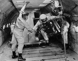 |
| Figure 82. Norman Shyken, McDonnell engineer-pilot, in zero-g tests in an Air Force KC-135 jet transport. (NASA Photo S-64-23051, May 25, 1964.) |
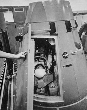 | 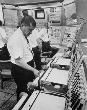 |
| Figure 83A. Astronauts Grissom and Young in the Gemini mission simulator at Cape Kennedy prior to the Gemini-Titan 3 mission. (NASA Photo No. 65-H-415, released Mar. 19, 1965.) | Figure 83B. Technicians at the mission simulator console. (NASA Photo No. 65-H-416, released Mar. 19, 1965.) |
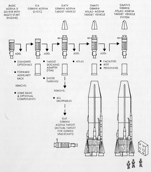 |
| Figure 84. Terminology for the Gemini Agena target vehicle program. (Lockheed, Gemini Agena Target Press Handbook, LMSC A766871, Feb. 15, 1966, p. 1-1.) |
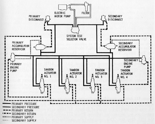 |
| Figure 85. Gemini launch vehicle stage I hydraulic system. (Martin Photo 8B65778, undated.) |
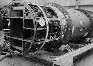 |
| Figure 86. Agena D 82 undergoing modification to Gemini Agena target vehicle 5002. (Lockheed Photo SA63603-C, Feb. 25, 1965.) |
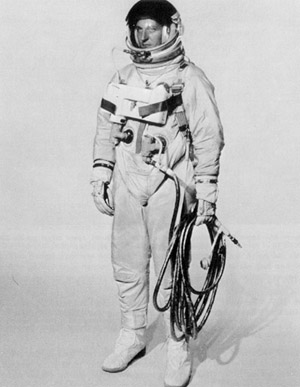 |
| Figure 87. The Gemini G4C extravehicular suit with chestpack ventilation control module and gold-coated umbilical line. (NASA Photo S-65-27424, May 28, 1965.) |


